Ciencia, Ingenierías y Aplicaciones, Vol. 6, No. 2, julio-diciembre, 2023 ISSN (impreso): 2636-218X • ISSN (en línea): 2636-2171 • Sitio web: https://revistas.intec.edu.do/
EFFECT OF SIZE ON MUTUAL IMPEDANCE COUPLING IN A SMART SWITCHED-BEAM ANTENNA ARRAY
Efecto del tamaño en el acoplamiento mutuo de impedancias de un arreglo de antenas inteligentes de haz conmutado
DOI: https://doi.org/10.22206/cyap.2023.v6i2.2987
LUIS FELIPE RIAÑO GALEANOa* & HERNÁN PAZ PENAGOSb
a Postgraduate student, Universidad Escuela Colombiana de Ingeniería Julio Garavito, Bogotá, Colombia. ORCID: 0009-0002-9012-9213, Email: luis.riano@mail.escuelaing.edu.co * Corresponding author.
b Professor, Universidad Escuela Colombiana de Ingeniería Julio Garavito, Bogotá, Colombia. ORCID: 0000-0002-2692-1989, E-mail: hernan.paz@escuelaing.edu.co
Received: 8/11/2023 • Accepted: 1/12/2023
How to cite: Riaño Galeano, L. F., Paz Penagos, H. (2023). Effect of size on mutual impedance coupling in a smart switched-beam antenna array . Ciencia, Ingenierías y Aplicaciones, 6(2), 81–104. https://doi.org/10.22206/cyap.2023.v6i2.2987
Abstract
This article presents the impact of array size on mutual impedance coupling in a switched-beam antenna array and its effect on link availability for communication between an UAV and a fixed ground station. Smart antennas are crucial in wireless applications, such as precision agriculture, where the direction of arrival of desired signals must be determined to optimize power reception through the array's radiation pattern. The study focuses on understanding the mutual coupling effects resulting from array characteristics, such as the number of elements and geometry, which can affect antenna impedance and consequently influence on SNR and link availability. The research aims to provide insights into the effect that the number of elements, the spacing between them, and the size or shape of each element in the array have on the lower or higher SNR values due to mutual impedance coupling.
Keywords:
Mutual impedance coupling; smart antennas; switched-beam antenna array; link availability; UAV-ground station link.
Resumen
En este artículo se presenta el impacto del tamaño de un arreglo en el acoplamiento mutuo de impedancias en un arreglo de antenas de haz conmutado y su efecto en la disponibilidad del enlace para la comunicación entre un dron y una estación terrena fija. Las antenas inteligentes son fundamentales en aplicaciones inalámbricas, como la agricultura de precisión, donde es necesario determinar la dirección de llegada de las señales deseadas para optimizar la potencia de recepción a través del patrón de radiación del arreglo. El estudio se centra en comprender los efectos del acoplamiento mutuo resultantes de las características del arreglo, como el número de elementos y la geometría, que pueden afectar la impedancia de la antena e influir en el SNR y la disponibilidad del enlace. La investigación tiene como objetivo brindar información sobre el efecto que el número de elementos, el espaciado entre ellos y el tamaño o forma de cada elemento en el arreglo tienen en los valores más bajos o altos de SNR debido al acoplamiento mutuo de impedancias.
Palabras clave:
Acoplamiento mutuo de impedancias; antenas inteligentes; arreglo de antenas de haz conmutado; disponibilidad del enlace; enlace dron-estación terrena.
1. Introduction
Numerous approaches have been suggested to mitigate the mutual coupling arising from surface waves in microstrip patch antennas. These methods encompass optimizing antenna design, applying dielectric layers to shield the patch, incorporating shorting pins in the substrate to counteract polarization currents, utilizing metamaterials known as wave absorbents that induce magnetic resonance and a band gap for enhanced insulation between the patch elements, employing dielectric structures as electromagnetic bandgap (EBG) structures between antenna elements, and implementing the defected ground structure (DGS) technique (Tunio, 2020).
This study aims to demonstrate the degradation of the signal-to-noise ratio SNR when the mutual coupling between elements is not considered in the design of a conformal space array. Additionally, it is well-known that array characteristics, including the number of elements and geometry, impact antenna impedance due to mutual coupling effects, thereby affecting link availability. This article studies the effects of the number of elements (array size) on mutual impedance coupling in a switched-beam antenna array, as well as its impact on link availability for communication between an UAV and a fixed ground station, and vice versa.
2. Theoretical Framework
2.1. Mutual coupling in antenna arrays
Mutual coupling is the electromagnetic interaction between the antenna elements in an array, as shown in Figure 1. The current developed in each antenna element of an array depends on their own excitation and on the contributions from adjacent antenna elements. Mutual coupling is inversely proportional to the spacing between the different antenna elements in an array. Mutual coupling in an array causes changes in the radiation pattern of the array and in the input impedance of the individual antenna elements in an array.
Figure 1
Mutual coupling phenomenon (Zhang, 2014)
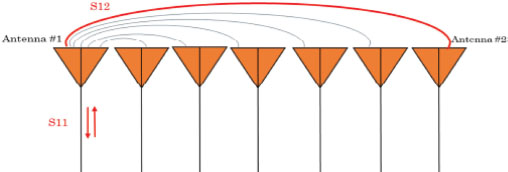
When two antennas are in proximity, and one of them is transmitting, some of the transmitted power will be received by the other antenna. The amount of power transferred to the second antenna depends on various factors, such as the geometric arrangement of antenna elements in an array (linear, planar, circular, substrate height, etc.), inter-element distance, signal excitation amplitude, signal excitation phase of each element, and the relative pattern of each element. In antenna arrays, the individual elements may receive the radiated fields from neighboring elements while simultaneously radiating themselves.
Furthermore, the received signal may undergo reflections, re-radiation, or scattering. This reciprocal interaction among the antenna elements gives rise to a coupling effect, thereby altering the array's characteristics. It is important to note that the fields generated by a particular antenna element affect nearby elements similarly to how they are influenced by neighboring element fields. Consequently, this coupling presence within the array leads to changes in terminal impedances, reflection coefficients, array gain, and beam width. The extent to which this coupling phenomenon impacts the array depends on factors like signal power, reflection coefficients, and additional electrical phase introduced due to propagation delay between elements (Tunio, 2020).
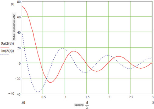
To characterize mutual coupling, can be used mutual impedance, S-parameters, a coupling matrix, or an embedded element pattern. Active impedance, or scan impedance, is the input impedance of each antenna element in an array, when all elements are excited. The active impedance of an array depends on the array configuration, the spacing between elements and the phase shift applied at each element. The effect of mutual coupling is observed or modeled by varying the space between the antenna elements in the array. Any change in the inter-element spacings changes the mutual impedance between the antenna elements. For example, the plot in Figure 2 shows the mutual impedance of a two-element dipole array as a function of inter-element spacing. It also shows that as the spacing between elements increases, the mutual impedance, and hence mutual coupling decreases. A coupling matrix is used to characterize the mutual coupling between the antenna elements at the port level. This matrix is calculated using S-parameters or Z-parameters and is used to decouple the array, depending on the number of ports in the array (MathWorks, 2023).
Figure 2
Mutual impedance variation in an antenna array with spacing (MathWorks, 2023)
A case where the usefulness of the Z-parameter matrix is visualized is in antenna arrays. An antenna exhibits a self-impedance Z11. If it is placed in the presence of another identical short-circuited antenna (parasitic antenna), the input impedance (Zin) can be calculated, considering that antenna 2 is short-circuited (V2=0), using Equation 1.
Considering that Z11=Z21 due to reciprocity, and the two antennas are identical, Z11=Z22, resulting in Equation 2
The conversion from impedance parameters Z to S-parameters is as follows in Table 1.
Table 1
S-parameters from impedance parameters Z
S |
Z |
S11 |
|
S12 |
|
S21 |
|
S22 |
The basis of the array theory is the pattern multiplication theorem. This theorem states that the combined pattern of N identical array elements is expressed as the element pattern times the array factor.
The array factor is calculated using the formula in Equation 3.
where:
• N is the number of elements in the array.
• V is the applied voltage (amplitude and phase) at each element in the array.
• k is the wave number.
• θ and φ are the elevation and azimuth angles.
• x, y, and z are the Cartesian coordinates of the feed locations for every antenna element of the array (MathWorks, 2023).
In large arrays, it is possible that the array directivity reduces drastically at certain scan angles. At these scan angles, referred to as the blind angles, the array does not radiate the power supplied at its input terminals. The scan blindness can occur while using these mechanisms: Surface wave excitation and grating lobe excitation. To detect scan blindness in large finite arrays, the embedded element pattern is used. In infinite array analysis, this pattern is known as the array element pattern (Stutzman, 2013).
The total field of the array is determined by the vector sum of the fields radiated by the individual elements. This indicates that the current in each element is the same as that in an individual element (without coupling). Usually, this is not the case and depends on the spacing between the elements. To achieve highly directive radiation patterns, it is necessary for the fields of the array elements to interfere constructively (sum up) in the desired directions and interfere destructively (cancel each other out) in the remaining space. Ideally, this can be achieved, but in practice, only an approximation is attained. In an array of identical elements, there are at least five characteristics that can be used to form the total antenna pattern, which are: the geometrical configuration of the total array (linear, circular, rectangular, spherical, etc.); the relative displacement between the elements; the amplitude of excitation of the individual elements; the phase of excitation of the individual elements and the relative pattern of the individual elements. Each of these aspects has a key influence on the overall radiation characteristics of the array (Balanis, 2005).
There is a wide range of substrates that can be used for microstrip antenna design, and their dielectric constants are usually in the range of 2.2 to 12. The most suitable substrates for good antenna performance are thick substrates with lower values of dielectric constant. They provide better efficiency, greater bandwidth, with minimal radiation losses into space, but at the expense of a larger element size (Kraus, 2003).
Thin substrates with higher dielectric constants are suitable for microwave circuits because they require fields that minimize unwanted radiation and coupling, leading to smaller element sizes. However, due to their higher losses, they are less efficient and have relatively narrower bandwidths. Since microstrip antennas are often integrated with other microwave circuits, a compromise must be reached between good antenna performance and proper circuit design (Balanis, 2005).
2.2. Space conformal antenna arrays
Space conformal antenna arrays are configurations where the elements are placed in specific three-dimensional locations to achieve precise control of the radiation pattern. Unlike planar arrays, space conformal arrays allow for greater flexibility in the direction and shape of the main beam, which is the case of this research. These arrays consist of a set of antennas placed at specific locations in space to achieve optimal performance in terms of gain, directivity, and frequency response. By distributing the antennas in precise geometric patterns, more precise control of the radiation pattern and beamforming is achieved. These arrays enable the formation of radiation beams in specific directions and shapes by precisely adjusting the amplitudes and phases of the array elements. This provides the capability to focus energy on areas of interest and minimize radiation in unwanted directions. Controlling the three-dimensional geometry of the array allows for high directivity, concentrating energy in the direction of the main beam, thus improving gain and sensitivity in that direction.
Furthermore, space conformal antenna arrays offer better ability to reduce interference from undesired signals. By focusing the main beam in the desired direction, radiated energy in other directions is minimized, reducing susceptibility to interference, and improving the signal-to-noise ratio. These arrays allow for adjusting the radiation pattern to adapt to different conditions and requirements. The shape, width, and direction of the main beam can be changed as needed to address various communication or detection scenarios. Unlike planar arrays, space conformal arrays can have a non-linear configuration, allowing for more design freedom and better adaptation to environmental constraints. Their ability to control and adapt the radiation pattern in three-dimensional space makes them a powerful tool for improving the quality and efficiency of wireless communications and sensing applications. This enables directing transmission and reception energy towards a specific direction, resulting in higher efficiency and transmission capacity.
2.3. Signal detection techniques
Direction of arrival (DoA) estimation is a detection method used in smart antenna systems where the goal is to determine the arrival direction of desired signals to maximize power reception, improve signal-to-noise ratio, mitigate interference, and enhance spectral efficiency. The characteristics of the antenna array, such as its geometry and corresponding differential array, have effects on aspects like mutual coupling phenomenon, DoA estimator accuracy, and array spatial resolution. The most important characteristics to consider in DoA estimation are precision, mutual coupling between sensors, and the number of user equipment (UE) that can be estimated in relation to the number of antennas in the array. The main objective is to minimize mutual coupling between the array antennas, making the structure more compact, and achieving better precision and the possibility of estimating more terminal equipment using the same number of antennas in the array. Significant reduction in the number of sensors in the array is sought, with minimal spacing between them, thereby minimizing mutual coupling (Zeng, 2016).
RSSI is a technique for detecting received signal strength that measures the power present in a signal and can be used to determine the location of a transmission efficiently and economically. It serves as an indicator of the power levels received by the receiver, meaning that higher RSSI values indicate a stronger signal. In an antenna array that utilizes this detection method, the RSSI of each element is monitored, and the system switches to the element receiving the highest signal level. RSSI and PoA (Power of arrival) are both based on received power levels, but they have significant differences. PoA assumes that the transmitting power and propagation path are already known, while RSSI does not require this information. It only works with the received power level and any differences that can be established between sensors (Cruz, 2017).
The RSSI detection technique is commonly used in wireless communication systems to determine the intensity of the received signal. It involves measuring the power of the received signal in a receiver and comparing it to a reference power. This comparison is made using a mathematical calculation that provides a measure of the signal's intensity in terms of dBm or V. High mutual coupling leads to malfunction in the smart antenna system, evident in errors in calculating the direction of arrival of signals, degradation in channel estimation, and problems in interference suppression through beamforming. On the other hand, the need arises to explore antenna geometries to improve features such as spatial resolution to serve more reception equipment with the minimum number of antennas in the transmitter array.
3. Methodology
To analyze the behavior of mutual impedance coupling in a microstrip antenna array at 3,5 GHz band, a methodology was followed where design and simulations were conducted to verify the operation of a communication system between an UAV and a fixed ground station using the required antennas. The objective was to characterize the parameters of the smart antennas and confirm the design of a switched beam microstrip smart antenna array located on the UAV. The implementation aimed to ensure proper communication with the fixed ground station through a microwave link.
Initially, individual microstrip antennas were designed on a suitable substrate from Taconic using MATLAB and CST Studio. Subsequently, the design of 4 and 6-element smart antenna arrays was performed using the same simulation tools to understand their behavior, particularly their radiation patterns and gains. After the designs and simulations, the construction of the antenna array follows, with its elements being identical to the ground station antenna. The switching algorithm is developed along with its respective programming on the Arduino processing board.
Subsequently, the integration of the bidirectional link system takes place, along with laboratory testing and any necessary adjustments to achieve the final system and evaluate mutual impedance coupling. It is essential to consider the input parameters of the system, the desired microwave bandwidths, and the mutual impedance coupling between all elements of the antenna array with the transmission line. It is ideal for the elements of the array to exhibit low impedances. Another important aspect is the size of the array, its efficiency, and the losses present in the link within that frequency band. After this process, each element of the array has a bandwidth of 35 MHz, a standing wave ratio (VSWR) of 1.02 level and a directivity of 7.6 dB.
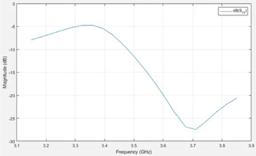
The antenna scattering parameter, also known as "Parameter S11," which is equivalent to the reflection coefficient for the antenna, is shown in Figure 3 corresponding to a value of -11 dB at a working frequency of 3.5 GHz. This value is equivalent to a return loss of 11 dB.
Figure 3
Scattering parameter S11 of the microstrip antenna on TLY-5 substrate
Each antenna in the array, in this case, has its elements arranged on the horizontal plane, and is a rectangular patch with the same dimensions as the individual microstrip antennas placed on a substrate with a relative permittivity of 2.2 (TLY-5), a thickness of 0.152 cm (TLY-5), and a loss tangent of 0.001. Consequently, the separation distance between the elements in the array is L=λ/4, with a value of λ = 0.085714 m = 8.5714 cm, making L = 8.5714/4 = 2.14285 cm the distance between elements. With orthogonal arrangement between elements for the 4-element array, and for the 6-element antenna array, the arrangement is at 60°.
The corresponding radiation patterns for each array are shown below, considering that the directivity values for the required frequency increase as the number of elements in the array increases. The simulation of the 4-element array is performed in Keysight's System Vue, based on the RF Phased Array template, and the obtained results are visualized in Figure 4.
Figure 4
Radiation pattern for the 4-element array in System Vue
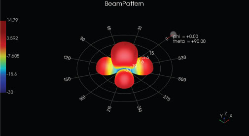
A maximum directivity value of 13.4 dB and a minimum directivity value of -32.1 dB are observed. Much of the radiated power is concentrated in the front of each element, with virtually no back lobes located on the ground plane side. Figure 5 shows the radiation pattern of the 6-element microstrip antenna array at a frequency of 3500 MHz on the TLY-5 substrate.
Figure 5
Radiation pattern for the 6-element array in System Vue
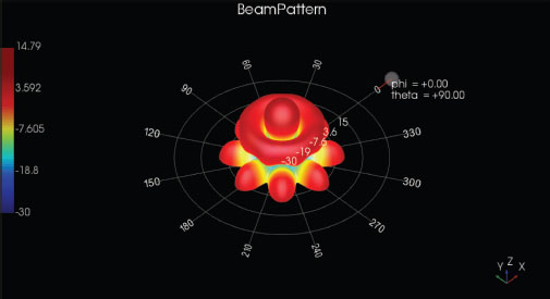
A maximum directivity value of 14.4 dB and a minimum directivity value of -24.6 dB are observed. Much of the radiated power is concentrated in the front of each element, with virtually no back lobes located on the ground plane side.
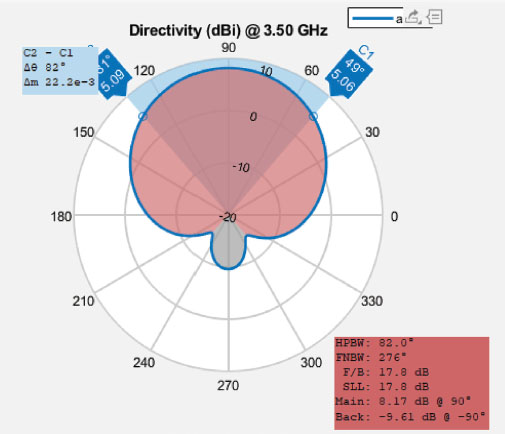
The characterization of the radiation pattern of the faces of both the 4-element and 6-element arrays was carried out to observe their behavior compared to the MATLAB simulations. For this purpose, the value of the half-power beamwidth (HPBW), which corresponds to the effective opening angle of the antenna, is determined. The simulated value of HPBW is equal to 82°, as shown in the Figure 6.
Figure 6
Half-Power Beamwidth (HPBW) for each element of the array in MATLAB
To perform laboratory tests in a controlled environment, which are shown in Figure 7, a protocol of physical tests was followed. Initially, the configuration of the fixed ground station that transmits a tone at 3.5 GHz is carried out, using the USRP 2954 RIO from National Instruments, controlled through LabVIEW Communications software with a PCI x4 connection. The connection of the antenna arrays with the Arduino Mega 2560 was carried out, which allows the detection of RSSI power levels received in each of the elements as the array rotates clockwise. The switching system is also connected, with the central element being the HackRF One transmitter, which transmits a tone from the array to the fixed ground station. The collection of received signal power levels (RSSI) is performed in the Arduino IDE algorithm, in a way that discriminates the highest power levels received in the element and switches the transmission of the tone generated by the HackRF One to that specific element.
Figure 7
Configuration of the tests for the arrays in the telecommunications laboratory

4. Results
The widespread adoption of patch antennas in the wireless industry highlights their significance due to their low profile, lightweight, cost-effectiveness, ease of manufacturing, conformal nature, and seamless integration into microwave circuits. However, when designing patch antenna arrays on thick and lossy substrates, additional considerations become crucial. In this scenario, the impact of mutual coupling becomes more prominent, occurring through two distinct mechanisms: coupling via surface waves and coupling via free-space waves.
The prevalence of specific coupling mechanisms, such as surface wave coupling or other types, depends on various factors such as the thickness of the substrate material, the characteristics of the ground plane, and the excited modes of the patch antenna. In certain scenarios, one coupling mechanism may outweigh the others. Notably, surface wave coupling tends to dominate when patch antennas are fabricated on high permittivity dielectric substrates and becomes even more pronounced as the substrate thickness increases.
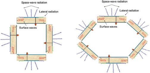
The dielectric substrate sustains surface waves that, upon reaching the edges of the ground plane, undergo diffraction and continue propagating within the arrays, as depicted in Figure 8. The mutual coupling mechanism in 4-element and 6-element patch antenna arrays involves the interaction between adjacent antenna elements. When the elements are close together, the electromagnetic fields generated by one element can influence the neighboring elements, resulting in coupling effects. In a 4-element array, each element interacts with three neighboring elements, while in a 6-element array, each element interacts with five neighboring elements. This mutual coupling affects the impedance and radiation patterns of the antennas, impacting their performance and overall array characteristics. Proper design and spacing are crucial to mitigate the effects of mutual coupling and optimize the array's performance in practical applications (Tunio, 2020).
Figure 8
Mutual coupling mechanism in 4-element and 6-element patch antenna arrays
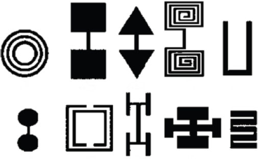
Defected ground structure (DGS) is a technique employed to create specific shapes, both symmetrical and asymmetrical, in the ground plane between antenna elements. These shapes are strategically designed to alter the propagation path of surface waves or modify the effective dielectric constant of the substrate, resulting in a frequency band elimination effect. DGS shares similarities with electromagnetic band gap (EBG) structures but offers the advantage of simpler manufacturing and requiring less surface area for implementation. Due to its band rejection capabilities and ease of integration, DGS has found widespread applications in various microwave circuits and antenna array designs. The diversity of DGS shapes and sizes is illustrated in Figure 9.
Figure 9
Examples of etched shapes geometries in arrays (Tunio, 2020)
The results obtained from the tests conducted to evaluate the switched-beam antenna array, located on an UAV, communicating via a microwave radio link with a fixed ground station at 3.5 GHz, aim to assess the functionality of the antenna array, link quality, and mutual impedance coupling. The bidirectional link quality at 3.5 GHz is evaluated based on parameters such as signal-to-noise ratio, link availability, and bandwidth. The antenna is switched, and the signal is received while the array rotates around the transmitter of the fixed ground station.
The signal-to-noise ratio (SNR) values can vary depending on the application and specific system requirements. For reliable error-free data transmission, an SNR of at least 20 dB is required for simple data applications (Tse, 2005), and for more demanding agricultural applications, such as video and images from the UAV. SNR was calculated only for the 6-element array, as according to the analysis of RSSI levels, the 4-element array did not meet the necessary characteristics to cover the 360° rotation.
Considering that the noise floor value detected by the N9000B in controlled laboratory tests is -90.15 dBm, the SNR value obtained for the 6-element array at 3 different distances from the ground station is shown in the Figure 10.
Figure 10
SNR of the 6-element array: 10a. SNR of elements 1 to 3; 10b. SNR of elements 4 to 6
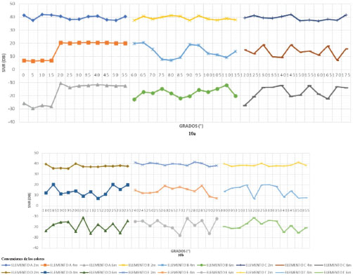
The x-axis of the graph represents the 360-degree rotation, and the y-axis represents the SNR values in dB for each element of the 6-element array, seen at distances of 2, 4, and 6 meters between the ground station and the array. This SNR value is calculated for the UAV-ground station link, which was the most critical in terms of RSSI levels.
At 2 meters, the obtained SNR values are within a range between 35 and 40 dB. At 4 meters, the SNR values range between 8 and 20 dB. However, at 6 meters, the SNR values are negative, fluctuating between -30 and -11 dB. Based on the selected parameters in the laboratory tests, it was observed that at 6 meters, the SNR values between -10 and -30 dB indicate that the link is not feasible, as reliable communication is not possible. SNR values equal to or greater than 20 dB only occur at distances of 2 and 4 meters between the ground station and the UAV. In these two cases, communication in the link is reliable.
An SNR below -10 dB indicates that the noise level in the system is higher than the level of the desired signal, making it challenging to distinguish the signal from the noise. This negatively affects the communication quality and the ability to reliably retrieve information. This situation may occur in environments with high electromagnetic interference, ambient noise, or when the signal has significantly attenuated due to distance. Link losses can also be caused by cross-polarization phenomena, where the transmitted or radiated electric field vector does not have the same polarization as the receiving element on the UAV, possibly due to slight tilting caused by relative vehicle motion, leading to less than 100% polarization coupling.
The relationship between these SNR values and mutual impedance is based on the existence of power reflections due to mismatching. The parameter that indicates this mismatch is S11, which reflects the link availability. The areas where there is no transition and illumination between elements are related to the size of the antenna array.
5. Discussion of results
The results of the evaluation of the 4 and 6-element switched-beam antenna arrays can be analyzed from different perspectives: the performance of the constructed antenna arrays and the link evaluation in terms of mutual impedance coupling. Initially, a switched-beam array was chosen because it offers controlled directivity, higher gain, reduced interference, beam flexibility, smaller size and weight, low interference between elements, and lower processing complexity required for achieving switching, as mentioned in the literature. The selection of 4 and 6 elements aimed to cover a larger space without increasing the number of elements excessively, which leads to better mutual impedance coupling, converging the array impedance towards the characteristic low impedance value of SMA-type connectors. This, in turn, ensures stable gain for the array, even though it results in a narrower beamwidth, thereby providing higher directivity. The goal was to have the array's beamwidth cover 360° and its directivity exceed 4 dBi.
As the number of elements increases, the gain and input impedance of the array also increase, leading to higher directivity and broader coverage. However, this also increases the complexity of the processing required for switching between elements.
The proximity between the elements in the arrays introduces changes in impedance due to mutual coupling, affecting the individual performance of each element and the overall radiation pattern of the array. This phenomenon of mutual coupling in arrays is also observed in Yagi antennas, where there is coupling between the director, reflectors, and the driven element, making it a common phenomenon in arrays of any type. This effect is evident in all antenna arrays.
The impedance coupling or impedance mismatch depends on the distance between one element of the array to another, their spacing and separation, the type of element, in this case, a patch element, which can vary if it's a linear element or a slotted patch.
In the laboratory tests, the results show that the link quality, as indicated by SNR levels for the 6-element array, ensures continuous communication at 2 and 4 meters of distance in the controlled laboratory environment. At 6 meters of distance and when RSSI levels are low, it should be noted that there is field dispersion in the transitions between elements, which explains levels below -3 dB that do not allow proper detection and switching, also caused by low effective area due to edge effects losses.
Considering the link evaluation, the results can be analyzed with the signal-to-noise ratio (SNR). In communication applications involving UAVs, the SNR plays a fundamental role in the quality and reliability of the communication. Due to the power limitations in UAV transmitters, it is crucial to use available power efficiently. Moreover, rapid wave dispersion at microwave frequencies, such as in the 3.5 GHz band, can cause signal fading, further affecting communication quality.
A pin-loaded patch antenna demonstrated superior performance compared to a conventional patch antenna in terms of suppressing surface waves and radiation in horizontal directions, resulting in improved directivity. Additionally, when these pin-loaded patch antennas are arranged in arrays with a specific separation distance between their feed points, they exhibit less coupled power compared to conventional patch antenna arrays aligned along the E-plane and H-plane orientations, respectively. To further reduce coupling, metallic walls can be introduced between the antenna elements to mitigate the effect of free space wave coupling. Combining the use of pins and metallic walls results in a greater reduction in the E-plane and H-plane, at the resonant frequency. Furthermore, this technique not only suppresses mutual coupling but also exhibits a wideband rejection characteristic of the transmission coefficient in both E and H-plane orientations.
6. Conclusions
Efficiencies in patch antennas refer to the antenna's ability to radiate or receive energy efficiently in relation to its physical area. The total efficiency of a patch antenna consists of two main components: radiation efficiency and surface efficiency. An antenna may have a radiation efficiency in the range of 80% to 90%. An ideal patch antenna would have a surface efficiency of 100%, meaning that all transmitted or received energy would be effectively utilized. However, in practice, losses in dielectric materials and coupling elements can reduce the surface efficiency to be between 80% to 95%. The performance characteristics of individual elements within an array are significantly impacted by mutual coupling when other elements are present. While analyzing isolated elements can provide valuable insights into certain parameters such as polarization, pattern shape, and resonant frequency, it is important to acknowledge that their behavior differs considerably when incorporated into the array geometry.
The proposed geometry of the 6-element switched-beam antenna array meets the defined criteria in terms of mutual coupling and spatial resolution, and it aligns with RSSI estimation methods from the literature. This was validated through RSSI estimation in a controlled laboratory testing environment that recreated a switched-beam smart antenna system mounted on an UAV. Regarding efficiency, gain, and impedance, the array performed as expected in the tests according to theoretical calculations and simulations. As the number of elements in an antenna array increases, mutual impedance between the elements tends to rise. Mutual impedance refers to the electromagnetic interaction between adjacent antennas in the array. As more elements are added, their proximity decreases, resulting in a greater influence of electromagnetic fields between the antennas. This interaction can lead to couplings and changes in the impedance characteristics of each element, altering its impedance and demanding coupling with the transmission line.
The increase in mutual impedance in arrays can have various effects on their performance and efficiency in radiating or receiving signals. Additionally, coupling between the elements can alter the radiation pattern of the array, as electromagnetic interference may cause changes in the distribution of radiated energy. It can also affect the gain and directivity of the array, as interference may lead to changes in energy concentration in the desired direction. To mitigate the negative effects of mutual impedance in an antenna array, measures can be taken, such as adjusting the geometry and spacing between elements, using impedance matching techniques, implementing coupling cancellation techniques, or applying adaptive beamforming techniques. These techniques help minimize the detrimental effects of increased mutual impedance and allow for improved overall performance of the antenna array as the number of elements is increased.
While patch or microstrip element arrays remain widely used due to their compact size, ease of fabrication, and ability to provide directivity and gain in specific applications, these limitations are continuously addressed with advanced design techniques. Techniques such as implementing coupling reduction, optimizing bandwidth, and enhancing radiation efficiency are utilized. The radiation coming from the feedline is a problem that limits cross-polarization and sidelobe levels of patch-type antenna arrays. Both cross-polarization and sidelobe levels can be improved by isolating the feed network from the radiating face of the array, which can be achieved using feeding probes or aperture coupling.
Finally, the bidirectional link between a patch antenna array on an UAV and a fixed ground station in the 3.5 GHz band offers reliable communication with an appropriate SNR value (>20 dB), adequate availability (95%), and effective coverage (80%). These features are essential for various applications, such as agricultural surveillance within precision agriculture, benefiting real-time data collection and enabling efficient and successful drone operation in a demanding wireless environment.
In conclusion, the size of a smart antenna array has a significant impact on the mutual impedance coupling in a switched-beam antenna array, which, in turn, influences the link availability for communication between an UAV and a fixed ground station. Laboratory tests conducted with a 6-element array demonstrated that at distances of 2 and 4 m, signal-to-noise ratio (SNR) values above 20 dB were achieved, ensuring reliable and continuous communication. However, at 6 meters, mutual coupling and field dispersion at element transitions negatively affected the SNR, resulting in values below -3 dB and unreliable communication Therefore, carefully designing the size and spacing of elements in the array is fundamental to achieve optimal mutual impedance coupling and ensure a high level of link availability, thereby enabling efficient and effective data transmission in precision agriculture operations using UAVs.
7. References
Balanis, C. (2005). Antenna Theory: Analysis and Design. Third Edition. New Jersey: Wiley-Interscience.
Cruz, W. (2017). Métodos AOA, PDOA e Híbridos para la localización de un transmisor no colaborativo mediante lanzado de rayos sobre un motor de juegos. [Tesis de maestría, Universidad Icesi]. Cali. https://dialnet.unirioja.es/servlet/articulo?codigo=9022835
Kraus, J. (2003). Antennas: for all applications. Third Edition. Singapore: McGraw-Hill.
MathWorks. (2023). Mutual Coupling – MATLAB and Simulink. Available at: https://la.mathworks.com/help/antenna/ug/mutual-coupling.html
Stutzman, W. and Thiele, G. (2013). Antenna Theory and Design. Third Edition. New York: Wiley.
Tse, D., y Viswanath, P. (2005). Fundamentals of wireless communication. Cambridge University Press.
Tunio, I. (2020). Study of impedance matching in antenna arrays. [Tesis doctoral, University of Nantes and University of Bretagne Loire]. https://hal.science/tel-03096564
Zeng, Y., Zhang, R. and Joon, T. (2016). Wireless communications with unmanned aerial vehicles: Opportunities and Challenges. IEEE Communications Magazine, 36-42. https://doi.org/10.1109/MCOM.2016.7470933